2.1.4.2 Azimuths, zenith distances and sets of directions (goniometric observations)
At extremely close ranges it is often difficult to observe distances with sufficient accuracy. Then angular observations offer an excellent alternative. But also for smaller image scales angular observations contribute strongly to network determination. Azimuths allow inclusion of gyroscopic measurements and may be used for network orientation.
Zenith distances considerably different from ±100 gon contribute to determination of point coordinates. The function used here

includes earth curvature, refraction and the difference (i-t) between height of instrument and target as correction terms.
The program applies the value of 6 380 000 m for the earth’s radius and 0.13 is applied for the refraction coefficient.
If metres [m] are not used as measuring unit, the value for the earth radius as input parameter has to be defined in the measuring unit chosen. The refraction coefficient can also be changed by input. The correction of earth curvature and refraction may also be omitted.
Each set of directions contains the observations  . The orientation unknown of a set of directions R0 with

connects the observations with the direction angles ϕ1, ϕ2, ..., ϕn., calculated from the approximate coordinates. BINGO applies the orientation unknown R0 for each set of directions as additional unknown. This procedure allows the use of different weights for the various direction measurements within a set of directions. This may be reasonable if (for example) it is difficult to aim at a target or if single targets lie extremely close to the station, since aiming is then relatively inaccurate.
The weights for survey observations are calculated from the a priori standard deviations which must be given by the user.
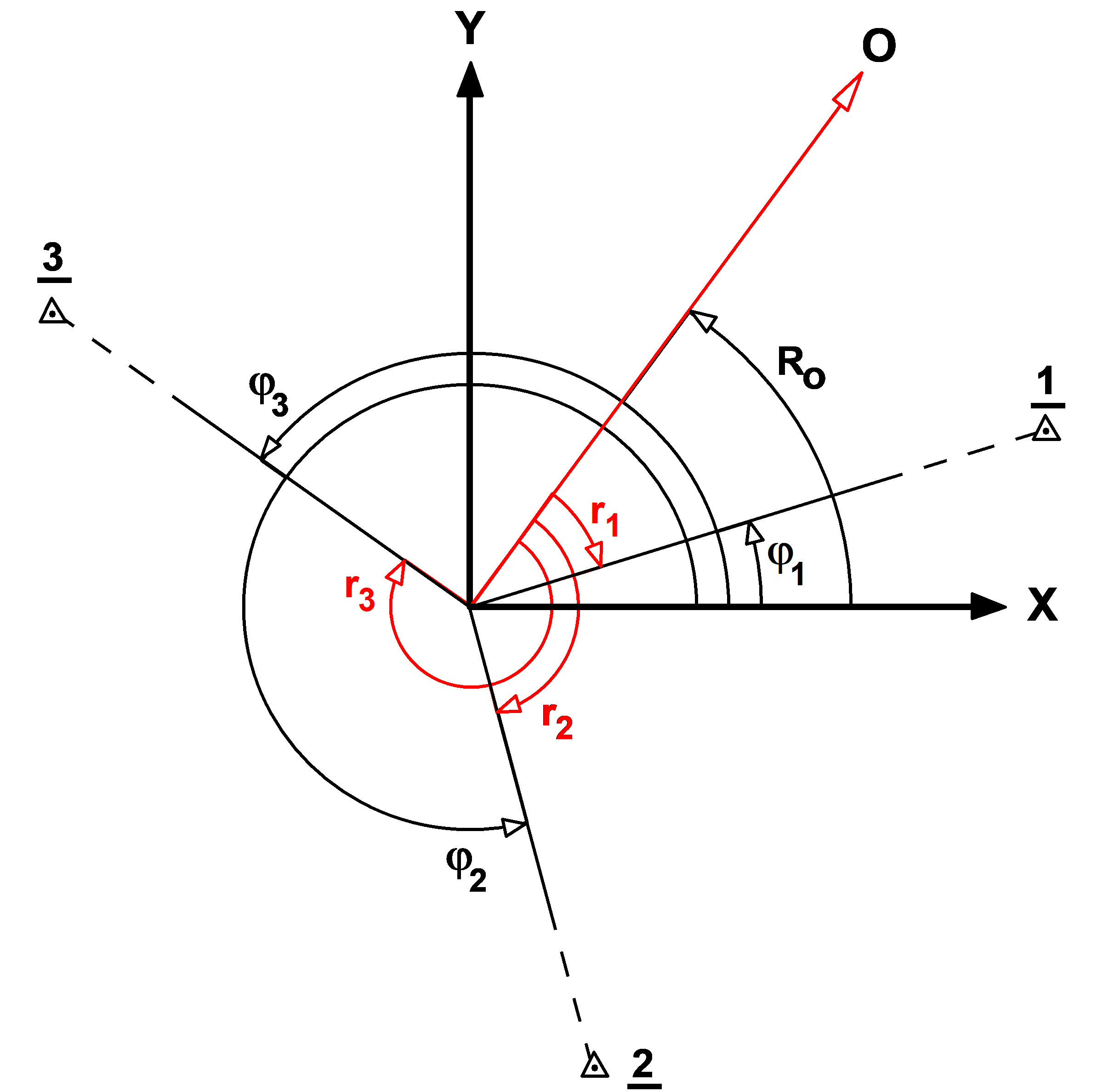
Fig. 2.1.4-1 Set of directions