ADPA Additional parameters
Columns | format | contents/explanation |
|---|---|---|
1-4 | A4 | ADPA (format free) |
| A | Camera name |
| A | Sensor type: ST=Sensortype (optional) Sensor type can be one of the following predefined names: DIMAC, DMC, UCD, UCX, UCE or RMK as well as UCDrota, UCXrota and UCErota if x' is perpendicular to flight direction (rotated camera definition). Input of one of these fixed names will lead to an automatic definition of the photo format and of the edges for each single CCD array of the camera. In case of DMC there are four, in case of UltraCamD (UCD) nine CCD-arrays. RMK means any aerial survey camera with a photo format of 230 * 230 mm². Now additional parameters can be given for every single CCD-array. The number of the CCD-array is multiplied by 100 and then added to the selected parameter number, for example parameter 3 for array no. 5 results in 503 as parameter number. |
| A | Parameter: SET=value |
| A | Keyword: LOCK |
| A | Format factor. FF=value (optional) |
| A | User-defined sensor type. UST=Filename (optional) if a sensor type for a camera with several CCD arrays is not pre-defined, a sensor type can be designated and the sensor boundaries specified individually in a file. For details see below. |
| nI | Numbers of additional parameters which are to be introduced as unknowns for the camera |
For one camera several ADPA statements may be indicated. Format factor or sensor type is only defined once however. Sensor type and user-defined sensor type are alternative entries and cannot be used together. The format factor can be used together with sensor type. Altogether 90 parameters with the number 1-38 are available for each camera (see Section 2.1.1.3 and Appendix A). It is not necessary to lay down a certain sequence of parameter numbers.
The parameters 1 to 24 are established for aerial photographs 23 * 23 cm². The parameters 7 to 10 correct the radial symmetric lens distortion. The parameters 25 and 26 or 35 and 36 are an alternative for the parameters 7 and 8. They differ from the parameter 7 and 8 by the second intersection point with the coordinate axis. But they have a higher correlation between each other than the parameters 7 and 8. The parameters 7 to 10 should not be used or only with great care in combination with parameters 25 and 26. The parameters 25 and 26 as well as 35 and 36 are more useful for rectangular photo formats and the parameter 7 and 8 more for squared photo formats. Parameter 39 is for radial distortion in form of several waves.
Parameters 9 and 10 are suitable only for square image formats. They should not be applied for rectangular formats, as otherwise distortions in the image centre might result.
Introduction of additional parameters to the adjustment should be done only after elimination of all gross errors in the block, and after good approximations for the unknowns are available in the ITERA file. See also Section 2.1.1.3 .
For the significance test of the additional parameters the a priori standard deviation will be used instead of the a posteriori standard deviation as long as this value is smaller than the a posteriori value. This is done in order to avoid a too early deletion of additional parameters in the first iterations.
Principally the chosen parameters are always valid for the whole photo format. For cameras combining several single frames of different CCD-arrays into one photo, it is necessary to calibrate every sensor individually. The position and boundaries of these sensors are known in BINGO for several cameras (see above). Figures 5.1-1 and 5.1-2 show the position and numeration of the CCD-arrays for two cameras.
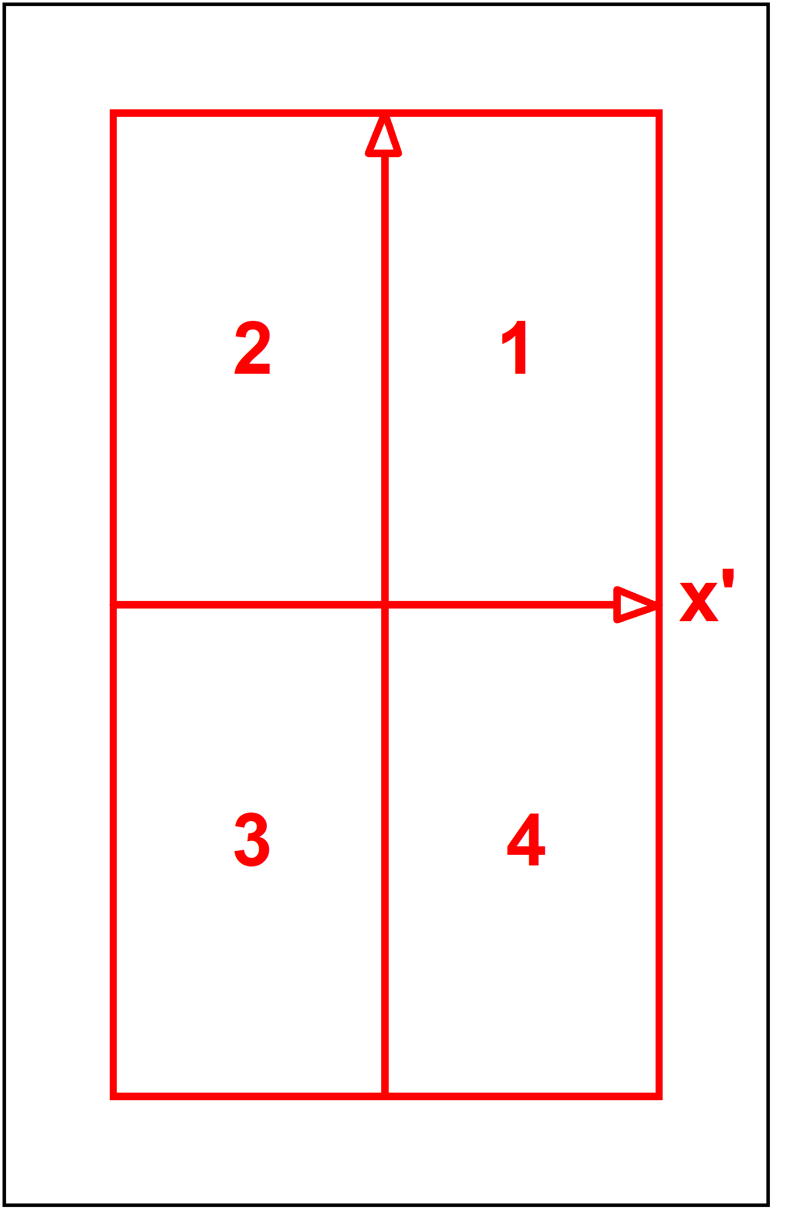
Fig. 5.1-1 Fragmental photos of a DMC
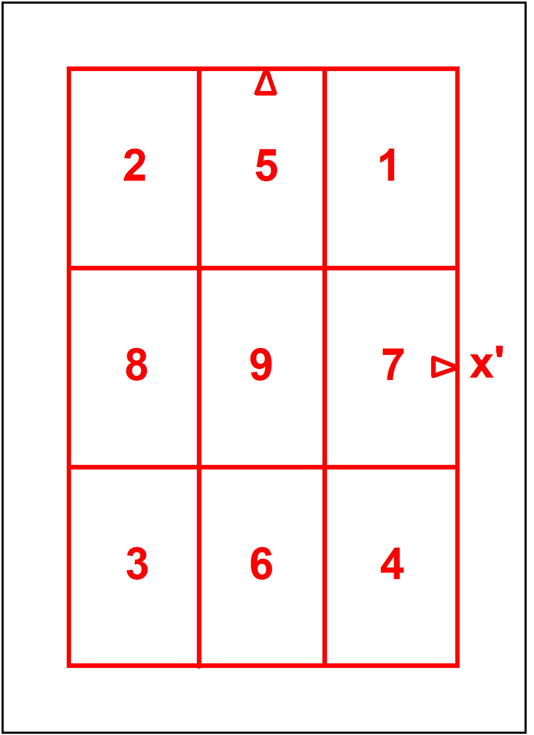
Fig. 5.1-2 Fragmental photos UltraCamD
In the event of one of the predefined sensor types, DMC, UCD, UCDrota, UCX, UCXrota, UCE, UCErota, RMK or DIMAC being indicated, fixed photo formats and therefore also fixed format factors will be applied. For all other cameras BINGO recognises the actual photo format for the camera from the given photo measurements. If this format differs from 230 * 230 mm², BINGO estimates a format adaption factor according to the chart below.
If the format does not apply to the chart, the factor will be chosen proportionally to the photo size. Alternatively a particular format factor can also be defined by entering it.
When the automatic elimination of redundant additional parameters is to be suppressed, the keyword "LOCK" can be used behind the sensor type. The effect will be applied to all cameras..
Format | Maximum x´ or y´ | Factor |
|---|---|---|
230 * 230 | 115 | 1.0000 |
180 * 180 | 90 | 1.2778 |
130 * 180 | 90 | 1.2778 |
90 * 130 | 65 | 1.7692 |
115 * 115 | 57.5 | 2.0870 |
60 * 90 | 45 | 2.5656 |
60 * 60 | 30 | 3.8333 |
45 * 60 | 30 | 3.8333 |
24 * 36 | 18 | 6.3889 |
18.1 * 27.4 | 13.7 | 8.3942 |
Format adaptation factor | ||
In the following, suggestions for parameter selection for the cameras UltraCamD and DMC are given.
UCE SET=1 | UCE SET=2 |
|---|---|
ADPA Cam1 ST=UCE 7 8 ADPA Cam1 117 131 132 134 ADPA Cam1 217 231 232 234 ADPA Cam1 317 331 332 334 ADPA Cam1 417 431 432 434 ADPA Cam1 517 531 532 534 ADPA Cam1 617 631 632 634 ADPA Cam1 717 731 732 734 ADPA Cam1 817 831 832 834 ADPA Cam1 917 | ADPA Cam1 ST=UCE 7 8 ADPA Cam1 117 131 132 ADPA Cam1 217 231 232 ADPA Cam1 317 331 332 ADPA Cam1 417 431 432 ADPA Cam1 517 531 532 534 ADPA Cam1 617 631 632 634 ADPA Cam1 717 731 732 734 ADPA Cam1 817 831 832 834 ADPA Cam1 917 934 |
Additional parameters for the UltraCamD | |
DMC SET=1 | DMC SET=2 |
|---|---|
ADPA 1 ST=DMC 25 26 ADPA 1 117 118 134 137 138 131 132 133 ADPA 1 217 218 237 238 ADPA 1 317 318 334 337 338 ADPA 1 417 418 437 438 | ADPA 1 ST=DMC 0025 26 ADPA 1 117 118 134 137 138 ADPA 1 217 218 234 237 238 ADPA 1 317 318 334 337 338 ADPA 1 417 418 434 437 438 |
Additional parameters for the DMC | |
The parameters suggested have the following meaning:
17 | Different scales in x' and y' |
18 | Share |
31, 32 | Shifts in x' resp. in y' |
33 | Rotation |
34 | Scale |
35, 36 | Radial symmetric distortion |
37, 38 | Special parameters for DMC |
As result of the self-calibration, BINGO writes the values of the additional parameters as APAV statements into the ITERA File. These rows can then be copied directly into the GEO INPUT File. Thus a once performed calibration can be applied for other projects.
User defined Sensor type:
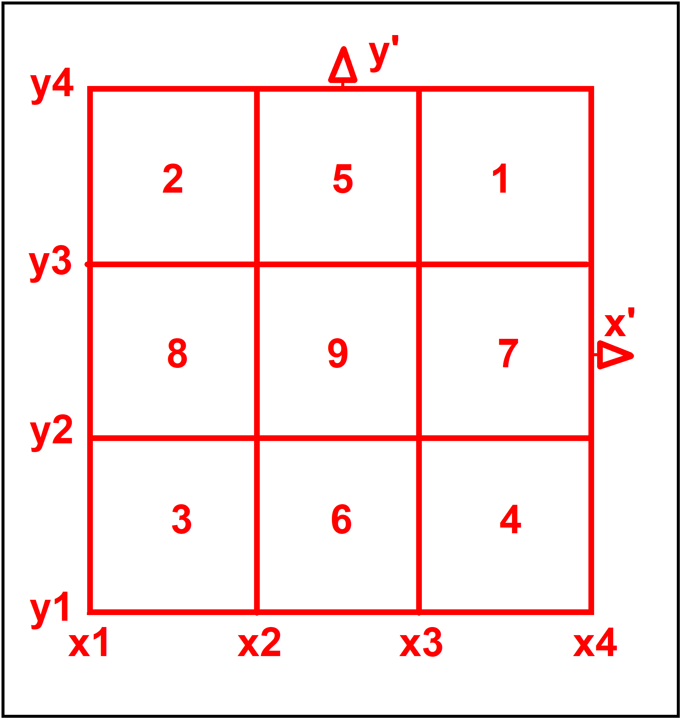
A user defined Sensor type can be made up of max. 3 x 3 CCD arrays (see Fig. 5.1-3). To define it a file with the following lines must be created:
Line 1: Line 2: Line 3: Line 4: | Name of the sensor type Format factor Sensor boundaries x1 x2 x3 x4 Sensor boundaries y1 y2 y3 y4 |
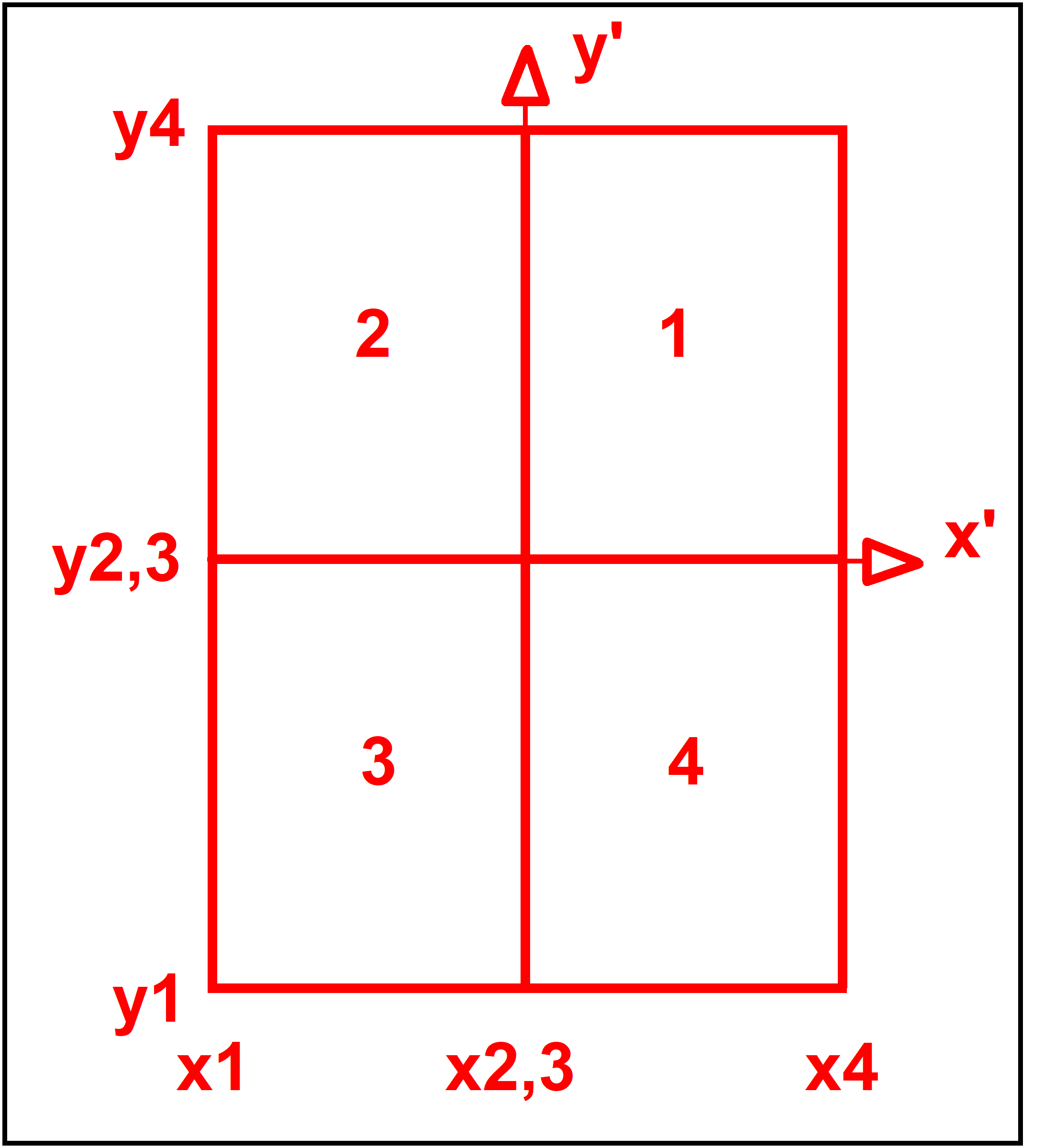
If there are less than 3 x 3 CCD arrays, the x- and y-values of the sensor boundaries should be chosen so that some of the CCD arrays tend to the value zero. In the following example for the DigiCAM with 2 x 2 CCD arrays, only the sensor areas 1, 2, 3 and 4 exist. The elements 5, 6, 7, 8 and 9 do not apply because their boundaries are zero. In this way any given sensor can be defined.
Fig. 5.1-3 |
| Example:
DigiCAM 2.286 -35.0 0.0 0.0 35.0 -50.3 0.0 0.0 50.3 |