BINGO 5.6
This page describes BINGO as it existed at the stated release date. For current behavior and requirements, use the current Manual, Reference, and Guides.
BINGO 5.6-beta1 and beta2 have been tested successfully, and we say ″Thank you″ to all beta testers for their support and for description of recognized problems. Now we can release the new software version. News and changes are described below.
BINGO Manager
The layout of the BINGO manager has been changed a little for easier use.
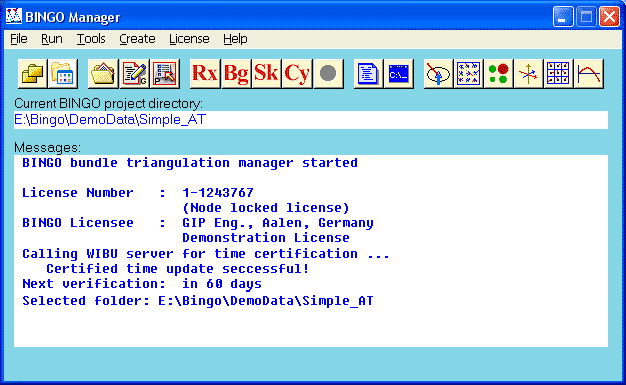
Fig.1 New layout of BINGO Manager
Display and recall of earlier projects is now working correct.
The problem to run the BINGO-SKIP-Cycle under Windows XP64-bit is now (hopefully) solved. The programs are normally not using pipes for communication anymore, but class IO.
The BINGO Manager creates a log file named BingoManager.log in the \Bingo\bin\ directory. Parallel to the message window, all activities will be written to this file. If the BINGO Manager session is closed, the file can be accessed.
If a new session is opened, the prior file will be renamed to old-BingoManager.log; earlier old-files will be deleted.
All manual files and read-me files can be opened from the Help menu.


Fig.2 Old projects to recall Fig.3 Access to document files
BINGO
All manuals are up to date
The maximum number of values in a RADI statement has been increased to 40.
The allowed number of additional parameters per cameras has been extended to 90.
In case of using files from another directory in any BINGO program related OLD-files will be created in the same directory as the original file. e.g.: using ..\image.dat in SKIP will lead to ..\old-image.dat .
The parameter Display (Show messages on screen) works now as described in the manual.
Additional output formats for orientation data are included: PhotoId, x, y, z, ω, φ, κ in grads and in degrees.

Fig.5 Additional output formats for orientation data
Bundle adjustment with one photo only is now again working correct.
The fatal error message ″Data not in ascending order of GPS time″ leads now only to a warning and not to a fatal message anymore.
Control points will be marked with ″Cont.Pt.″ in file imresi.dat.
In case, focal length and/or principal point are unknown parameters, the program gives a warning message, if no standard deviations are defined for these unknown parameters:
W242 Principal point of camera nn is unknown parameter. No standard deviation defined
If the option is set to remove two ray points from the bundle adjustment, control points and network points are not effected from this option in all earlier BINGO versions.
Now, as well those two ray points will be kept, which are seen in any photo at the end of a flight line. In this sense as well photos before and after a gap (one or more photos missing) in the flight line are at the end of a flight line (the program checks the base length). Precondition for this functionality:
All photo orientation data are already available in the itera.dat file.
All photos of the block have aerial orientation.
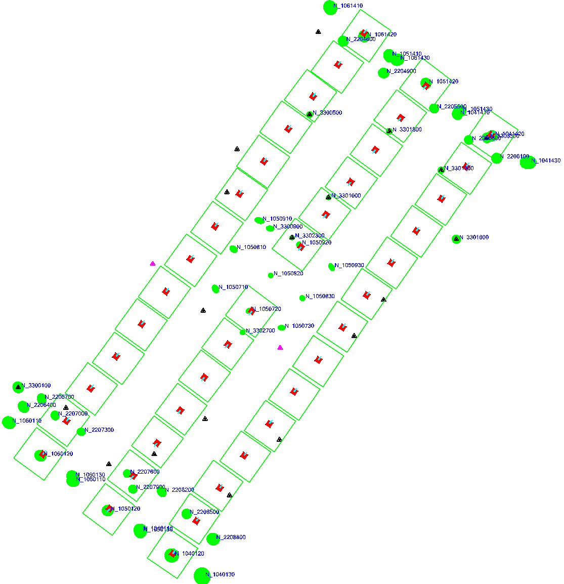
Fig.4 Remaining two ray points at the ends of flight lines (One photo is missing in the middle flight line.)
Important Note
The numbering of photos has to be done carefully to allow BINGO to recognize the flight lines: Numbering within a flight line has to be in ascending or descending order. No other photo number has to be within one flight line. If the strip number is added to the photo numbers, the photo number should have always the same number of digits!
The first numbering shown left hand side would lead to an image list as shown at right hand side. Flight lines, 4 and 5 would be interrupted between photos 9 and 10.
A camera definition file can be created to define the sensor limits and settings of any multi-sensor cameras say MSCN or AIC4. This allows strong definition and usage of any multi-sensor camera with 2x2, 3x3, 2x3 or 3x2 sensor arrays.
To avoid confusion, ″format factor″, ″sensor type″ and ″user defined sensor type″ have to be introduced with a preceding keyword in the ADPA statement as follows:
            ST=SensorName           any predefined name like e.g. UCX
            FF=value                new format factor
            UST=FileName            name of camera definition file
This differs from BINGO 5.5! See manual (ADPA statement) for more details.
Examples:           ADPA   cam27   UST=filename   25  26
                ADPA   cam27   ST=DMC   25  26
Camera File:        SensorName
FormatFactor
x1 x2 x3 x4
y1 y2 y3 y4
BINGO will confirm reading of this file with:
>>> Camera definition file ″filename″ successful read.
The format factor has to be estimated as ff = 230 [mm] / ss [mm] where ss is the longest sensor side.
For a standard DMC the file would be e.g.:
DMC
1.3864
-46.080 0.000 0.000 46.080
-82.944 0.000 0.000 82.944
For a standard UCD the file would be:
UCD
2.2222
-34.000 -10.935 10.935 34.000
-52.000 -16.875 16.875 52.000
(For standard DMC and UCD no definition file is required, because the data are already known in the program.)
If no camera definition file is needed, the format factor can be entered as well in the ADPA statement with a preceding ″FF=″.
For a 120 x 160 mm² camera an ADPA statement could be introduced e.g. as:
ADPA cam1 FF=1.4375 25 26
RELAX
Normal aerial survey cameras have radial symmetric distortion values below 10 µm. For those cameras it is not necessary to apply any given radial symmetric lens distortion during estimation of initial orientation value.
But since short time as well aerial cameras with high radial symmetric lens distortion are used for photogrammetric projects. These distortion are in some cases more then 100µm. If those high distortions are not applied to the photo coordinates during estimation of initial orientation values, orientation data will be falsified as shown below. The control points do not fit to the data anymore and during iteration in BINGO no convergence can be reached.
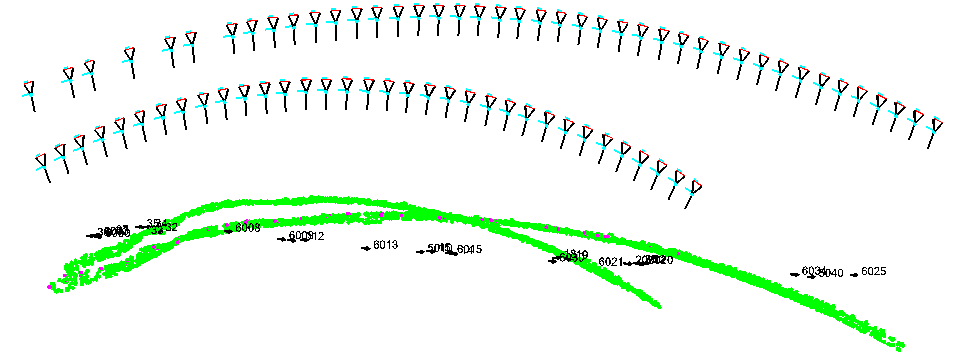
Fig.6 Falsified initial orientation data. Lens distortion is not applied.
Given radial symmetric lens distortion values will therefore now applied as well in program RELAX during relative orientations. As result we get correct orientation values, and the control points fit to the block.

Fig.7 Correct initial orientation data. Lens distortion is applied.
SAMBA
The default values have been increased to hold more points per section.
ROMA
Sequence of operation is now selectable to provide more flexibility.

Fig.8 New function in ROMA
IMPLO
In addition to the image distortions for all images in one frame, program IMPLO can now display as well the point distribution of the image points. Usage is specially recommended, if a sensor type like UCX or DMC etc. has been defined for additional parameters. In conjunction with the ADPLO graphic, which is showing the single CCD elements, correct application (especially the image rotation) can be checked easily.
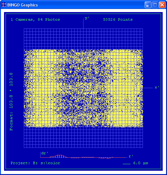
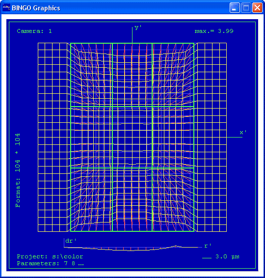
Fig.9 IMPLO graphics and ADPLO graphics. The image orientation is not correct for the selected sensor type UCX. For BINGO processing, image orientation has to be corrected first. E.g. using program ROMA.
ImgView
A new graphics program has been added to the BINGO tools to view photo measurements, image residuals, missing measurements ...
A button has been added to the BINGO Manager to start the program.

Fig. 10 New button for to start program ImgView
This program displays image measurements, image residuals, point IDs, number of photo rays, skipped and missing photo measurements for single images, groups of images or all images together in one frame.
Measured control points are displayed with a red triangle, other points with a blue circle. Vector color is according to the number of asterisks for each observation as follows:
green:  measurement has 0 or 1 '*' asterisk
blue: … measurement has 2 asterisk
magenta:    measurement has 3 asterisk
red:        measurement has 4 asterisk
Skipped points are displayed in light red or light blue according to the point type. Their residual vectors have grey color.
Missing points are points which should be visible within the photo frame. However, they are not measured. They will be displayed in light grey. Estimation of those points is only possible, if the itera file is available.
Point IDs and number of rays have the same color as their symbols.
IF "Show number of rays" is selected, the number will be displayed beside the point symbol (in front of point IDs). If the point is seen in more then one flight line, a '+' plus sign in front of the number of rays will indicate this.
Use "Settings" in the menu to select files and load data: Either files itera.dat and imresi.dat or file image.dat. Usage of the image.dat file is recommended, if the other two files are not yet existing.
"Save" will write the ImgView.ini file in the \Bingo\bin\ directory.
The window can be easily resized and moved. After next start, position, size and settings will be the same as at the time, the last window has been closed, or "Save" has been used. To go back to all default settings, push "Default" in the menu and close the window.
In case the BINGO Manager changes directory, or BINGO has been processed anew, please push "Reload" in the menu to load the latest data.
Hint:
To view more images at the same time, please start several instances of ImgView, arrange them on screen (e.g. three images of one flight line beneath each other) and select first image number in the first window, second image number in the second window etc. Now push the "All +1" button. All your windows will display the content of the next image.
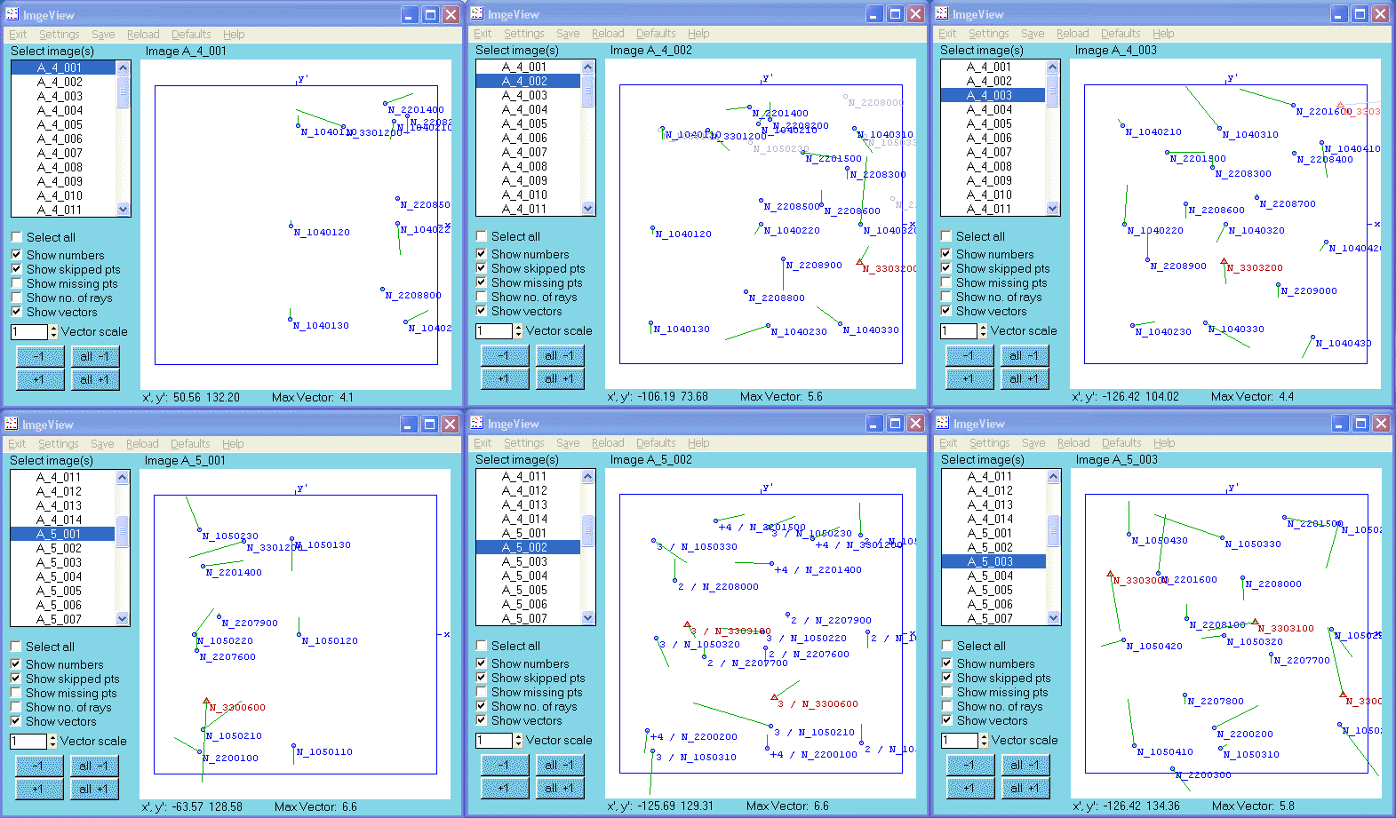
Fig.11 Viewing photo measurements and residuals of three photos in two neighboured flight lines.
3dView
The program has been extended to display as well the residuals from HEL3D transformation or data comparison. (Using file hel3d.lis instead of reselli.dat.)
Three more check boxes have been introduced for new graphical presentations.
The first new box is to display the connections between the photos. The color of the connection lines is related to the number of homologous points between these photos:

   grey 1  or  2  common points
   cyan   common points
   yellow   6 or more common points
This feature is very helpful to recognize poor connections in a bundle block.
The second box is to see all rays from photos to control points in a block at once. Skipped rays will be displayed in red color.
The third box changes colors of foot prints. Six different color will be used in a cycle. Colours will change at the beginning of every flight line. For correct recognition of flight lines see the note in section BINGO.
Examples:
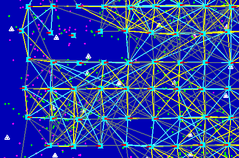
Fig.13 Insufficient connection between photos

Fig.14 Because of clumsy photo numbering, program cannot recognize flight lines

Fig.15 Some control points should be visible in more images.